You are here: Home » Testing & Characterization » Surface Analysis » Corrosion
Corrosion
Corrosion on any item can lead to long term product failure or yield loss. At Lucideon, our experts can determine the cause of corrosion and thereby suggest ways of preventing it. We are also able to potentially detect corrosion products before the appearance of visual evidence.
Rusting, discoloration, tarnishing, pitting, oxidation.
Cause:
- Chemical residue from the manufacturing process
- Surface contamination from handling
- Unsuitable packaging e.g. chemical reaction with volatile components, transferable residue
- Environmental conditions during material/product storage
- Environmental/test conditions experienced by the material/product in application
- Incompatibility with other components during material/product life e.g. preferential corrosion
- Improper passivation treatment
- Damaged protective coating.
Analysis:
- X-ray Photoelectron Spectroscopy (XPS) - to evaluate the chemical composition of the corroded surface in order to investigate the cause; provides quantitative elemental and chemical/oxidation state information for all elements except H and He.
- Secondary Ion Mass Spectrometry (SIMS) - to evaluate the chemical composition of the corroded surface in order to investigate the cause; in static and/or dynamic modes - the former is highly surface sensitive providing both inorganic and organic information, the latter can be used to profile through the corrosion layer(s) and investigate the elemental composition with depth.
- Complementary technique: Scanning Electron Microscopy with Energy Dispersive X-ray analysis (SEM-EDX).

Case Study:
Corrosion of Device Wafers
Corrosion of semiconductor devices during fabrication or after packaging and shipment can lead to serious yield loss or long term product failure. In this case study, corrosion has occurred on bond pad regions and surrounding line features after wafer storage. Optical microscopy and DSIMS analysis have been used to identify the nature and cause of corrosion.
- Optical microscopy examination at Lucideon revealed a concentration of corrosion sites and staining around the wafer edge.
- SIMS mass spectral analysis revealed the presence of ionic residues including sodium, potassium, fluorine and chlorine in corroded/stained areas.
- SIMS imaging of contaminant distributions shows high localised concentrations of ionic residues in and around corrosion sites.
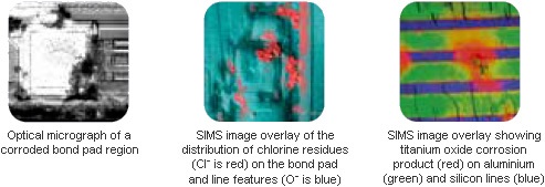
SIMS mass spectral and imaging analysis revealed ionic residues remaining in wafer edge areas after insufficient washing. The resulting corrosion of titanium silicide leads to titanium oxide formation and ultimately wafer rejection. An improved washing / drying procedure would lead to significant improvement in wafer rejection.
Case Study:
Corrosion Problems on Steel Wires
Localised corrosion had appeared on reels of wire after long term storage but investigations by the manufacturer had shown no correlation between the problem and the materials used. These included steel, drawing lubricants and post-drawing, lanolin protective coating. XPS compositional analysis (below) of corroded and uncorroded areas, at Lucideon, shows a significantly higher concentration of iron in the corroded areas coupled with lower levels of calcium and sodium from the drawing lubricants (a mixture of calcium and sodium stearates).
XPS Surface Compositions (Figures in Atomic%)
| Analysis Area | Carbon | Oxygen | Iron | Calcium | Chlorine | Sodium | Sulphur |
| Corroded | 35.4 ±1.2 | 50.8 ±1.1 | 8.1 ±0.4 | 3.5 ±0.3 | 0.9 ±0.4 | 1.3 ±0.5 | - |
| Uncorroded | 38.9 ±0.8 | 46.0 ±0.7 | 4.3 ±0.2 | 6.2 ±0.2 | 0.5 ±0.2 | 3.4 ±0.4 | 0.7 ±0.4 |
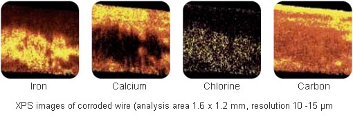
XPS images of a corroded area show an exposed iron area (rust) covering the lower part of the wire.
The corrosion areas are associated with striations along the wire in the drawing direction. Surrounding
areas are rich in carbon, calcium and sodium residues from the drawing lubricants. The chlorine
distribution correlates with iron suggesting an association between the two.
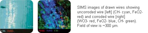
SIMS imaging analysis (below) showed that all corrosion areas contain tungsten (as tungsten oxide), as a result of the break-up of the wire-drawing dies during processing. The combination of XPS and SIMS analysis proved that corrosion arises as a direct result of a reduced level of lubricant during wire drawing which also causes the break up of the drawing dies. The reduced level of organic material and the roughening of the surface leaves the steel exposed to attack by classical aqueous corrosion, accelerated by the presence of chlorine.
Case Study:
Investigation of Corrosion Regions on Printed Circuit Boards (PCBs)
The purpose of this analysis was to identify the cause of corrosion appearing between integrated circuit contacts, resulting in circuit breakdown and board failure. The problem was mainly experienced in overseas installations where prevailing climatic conditions impose high levels of heat and humidity on the PCBs. Accelerated humidity testing reproduced the corrosion problem where corrosion product was appearing particularly between the legs of narrow pitch SMT Integrated Circuits (see typical pictures below).
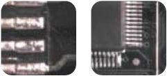
In addition, on boards which failed inspection tests, there was evidence of white staining and dendritic growth features on bare areas away from solder points and contact areas.
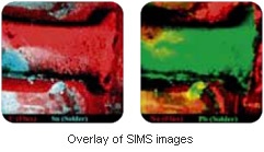
Combined XPS and SIMS analyses were carried out on a corrosion area between the SMT legs. These showed the presence of a complex mixture of inorganic ionic salts, organic residues and elements such as sodium, calcium, etc. The ionic salts included copper chloride, tin fluoride, lead fluoride, calcium fluoride and also oxy-halide species of tin and lead. The organic species were suspected to correspond to flux residues. The lateral distribution of selected species in a space between SMT legs are shown in the SIMS images below.
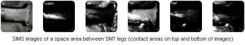
The presence of significant levels of elements such as sodium, calcium, fluorine, chlorine, tin and lead in the space between the SMT legs remaining after board production were believed to provide a basis for chemical processes resulting in the formation of the corrosion products described above. With the presence of water (acting as an electrolyte) from high humidity levels and heat (either from ambient conditions or generated in circuitry), the corrosion process may have proceeded through different ways such as redox reactions, galvanic processes, electrolysis via applied e.m.f between IC contacts, atmospheric oxidation, ionic salt formation or ion transport. The detection of copper in the corrosion product suggested ion transport (Cu2+) from the IC contacts or an underlying PCB track.